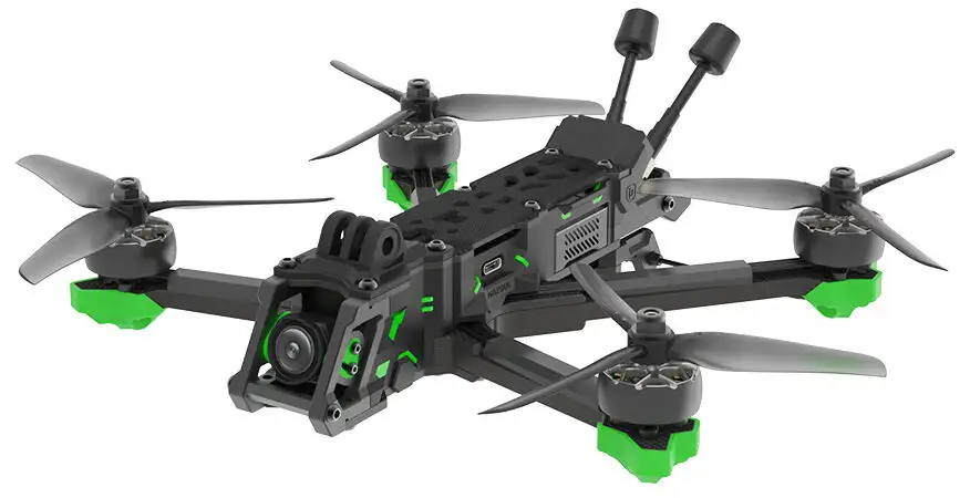
The iFlight Evoque F5D comes with a BLITZ MINI F7 fight controller.
1. Advanced ViSense Technology
ViSense-based technology, the VIFLY Finder 2 can power itself to beep even the quad battery has been ejected. Even more, the built-in light sensor can detect light intensity and then smartly control the LED light to flash. Besides, it enables the buzzer automatically enter into sleep mode at night to save power and not disturb.
2. Much Louder than Standard Buzzer**
To easily find the lost drone in long distance, the VIFLY Finder 2 buzzer is designed to install a very loud beeper that the volume can be up to 110 dB. ###
3. Two Options to Disarm the Buzzer
Option 1, Disarm with button: Disconnect main battery, hold disarm button on VIFLY Finder 2 for 1-5 seconds then release.
Option 2, Disarm with main battery: Disconnect main battery, then connect main battery for 3-6 seconds and disconnect it again. It will beep 3 times when disarmed successfully.
4. Compatible with Both FPV quadcopter and RC Airplane
VIFLY finder 2 is programmed to be compatible with any flight controllers to support FPV quad, and receivers for RC airplane. No extra setting required, it will automatically recognize the device to connect. ##
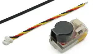
VFLY 2 drone finder beeper
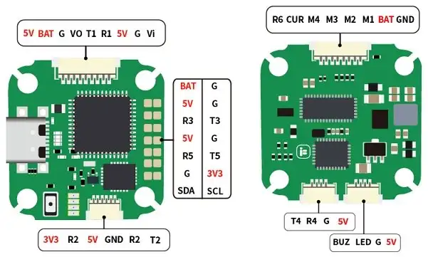
We will wire a VIFLY buzzer to the iFlight BLITZ Mini F7 FC as follows: * GND from the VIFLY buzzer to the G pin on the FC. * BZ+ from the VIFLY buzzer to the 5V pin on the FC. * BZ- from the VIFLY buzzer to the BUZ pin on the FC. All pins are in the same 4-pin socket on the FC as the LED pin.
BLITZ Mini F7 V1.1 Flight Controller
These are the pins in that socket…
- BUZ
- LED
- G
- 5V
So wire as described below. You are only connecting one wire to each pin in the socket. (VIFLY) Buzzer Wiring:- * GND from the VIFLY buzzer to the G pin in the socket on the FC. * BZ+ from the VIFLY buzzer to the 5V pin in the socket on the FC. * BZ- from the VIFLY buzzer to the BUZ pin in the socket on the FC. LED Strip Wiring:- * GND from the LED Strip to any G pad on the FC (soldered). * 5V from the LED Strip to any pad on the FC (soldered). * DI / DIN from the LED Strip to the LED pin in the socket on the FC. ## Assign a switch in Betaflight, Here SC for the Radiomaster ZORRO

The SC switch is located on the top right
